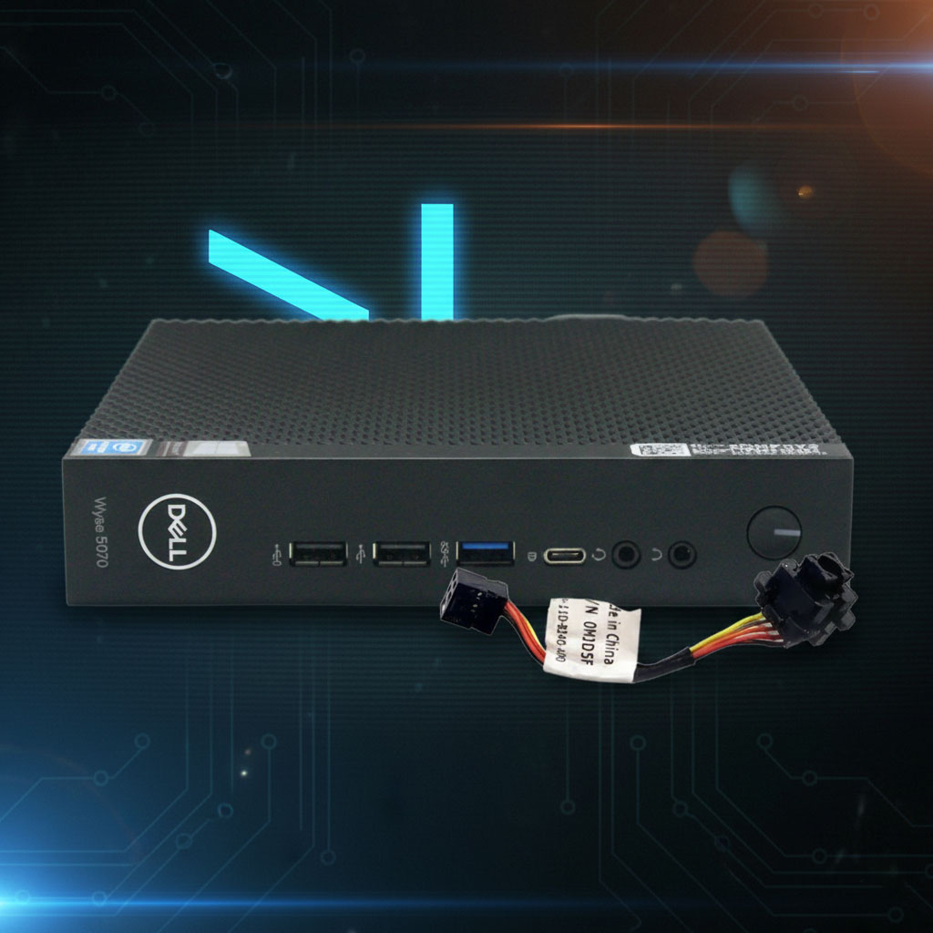
After several years of steady service, the white power-on LED indicator on my Dell Wyse 5070 Thin Client finally gave out. Interestingly, the orange standby/error LED still worked, but the white “active” light was dead.
I discovered the failure after a recent power outage. I run this unit “headless” (without a monitor) as part of my Home Lab, where it serves as a Network UPS Tools (NUT) server. It monitors my UPS and signals my ESXi server to gracefully shut down virtual machines when the battery is low. Because this little PC is critical to my lab’s safety, I need to know at a glance if it’s running.
When I saw the LED was dark, my first thought was “Oh no!” Fortunately, I quickly realized the PC was fine—only the white LED had failed. After searching online, I found this is a common issue with the 5070, yet there were almost no practical solutions available.
In this post, I’ll show you how I replaced the faulty LED for just a few cents.
Parts Required
3mm Bi-Color LED (2-pin): Ensure you get the White/Amber (or White/Orange) variety. These are “bipolar” or “non-polar” LEDs, meaning they change color when the polarity of the current is reversed.
Solder: Standard electronics-grade solder.
Tools Needed
Screwdriver: A standard Phillips #1 or #0.
Soldering Iron: A fine-tip iron is recommended for the small PCB pads.
Desoldering Tool: A solder sucker or desoldering wick to clear the original holes.
Dremel, Precision File or Sandpaper: To shave down the 3mm LED housing and flange.
Hobby Knife (X-Acto): For modifying the plastic grooves and clearing the silicone potting material.
Wire Cutters: To trim the LED legs after soldering.
Optional (Heated Blade): Useful for removing the hard silicone around the original LED.
1) Removing the Power Button Assembly
Before starting, shut down the PC and disconnect the power cable.
Open the Case: Unscrew the single Phillips screw on the back panel and slide the top cover off.
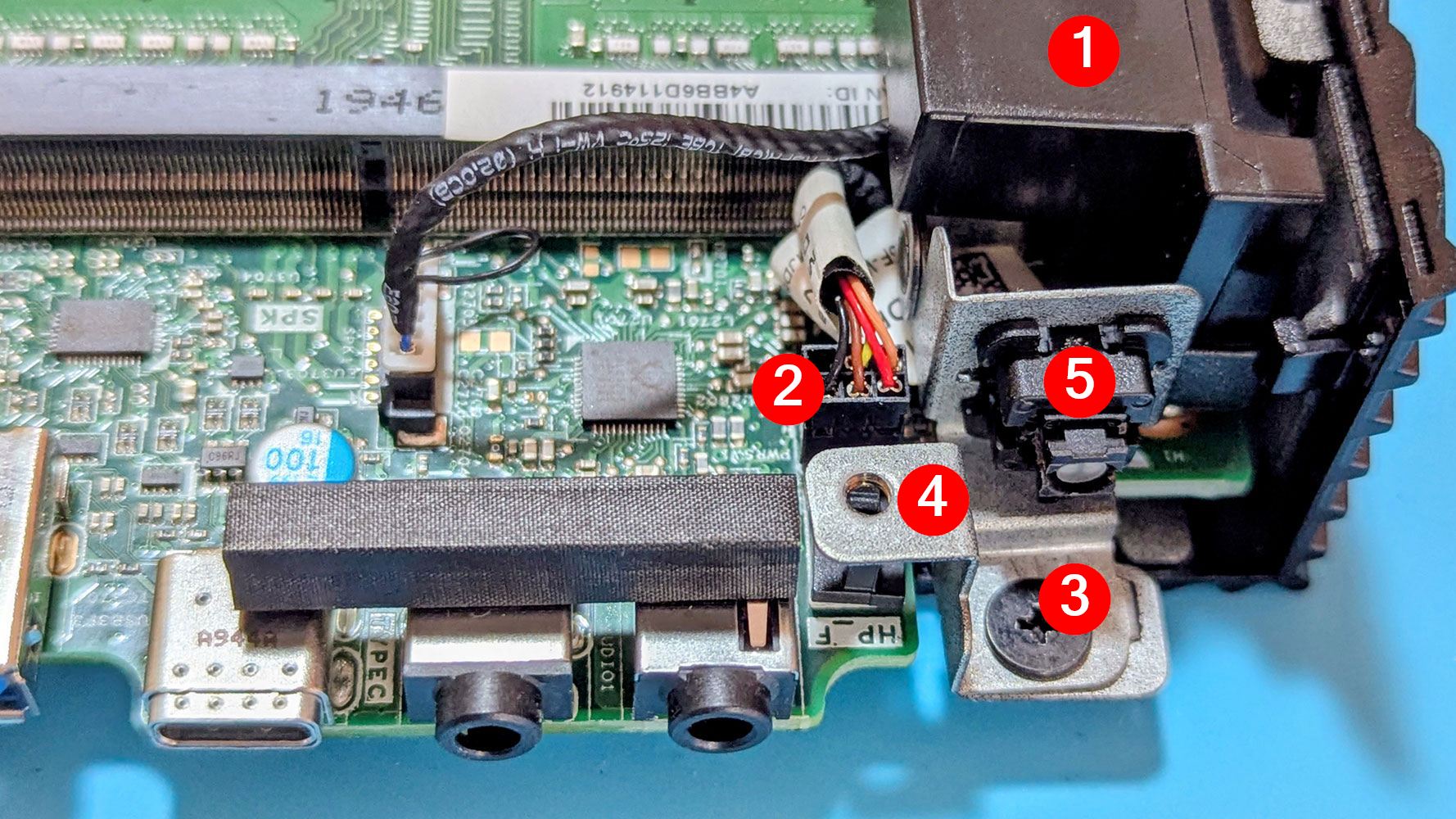
Remove the Speaker: Carefully lift out the speaker ①.
Disassemble the Bracket: Pull the connector ②, then remove the small screw ③ holding the power button bracket ④. Lift the bracket to disengage it from the chassis.
Isolate the Button: I found it easier to remove the actual button ⑤ from the bracket for easier handling during the repair.
2) Removing the Faulty LED
The LED is integrated into the power button. The Dell part number for this cable assembly is 0MJD5F. These are difficult to find new and surprisingly expensive on the used market—with no guarantee they won’t fail again.
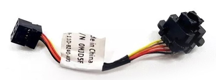
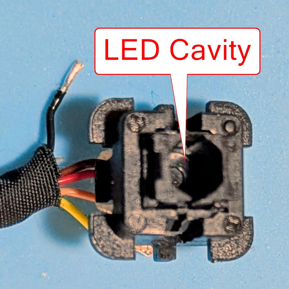
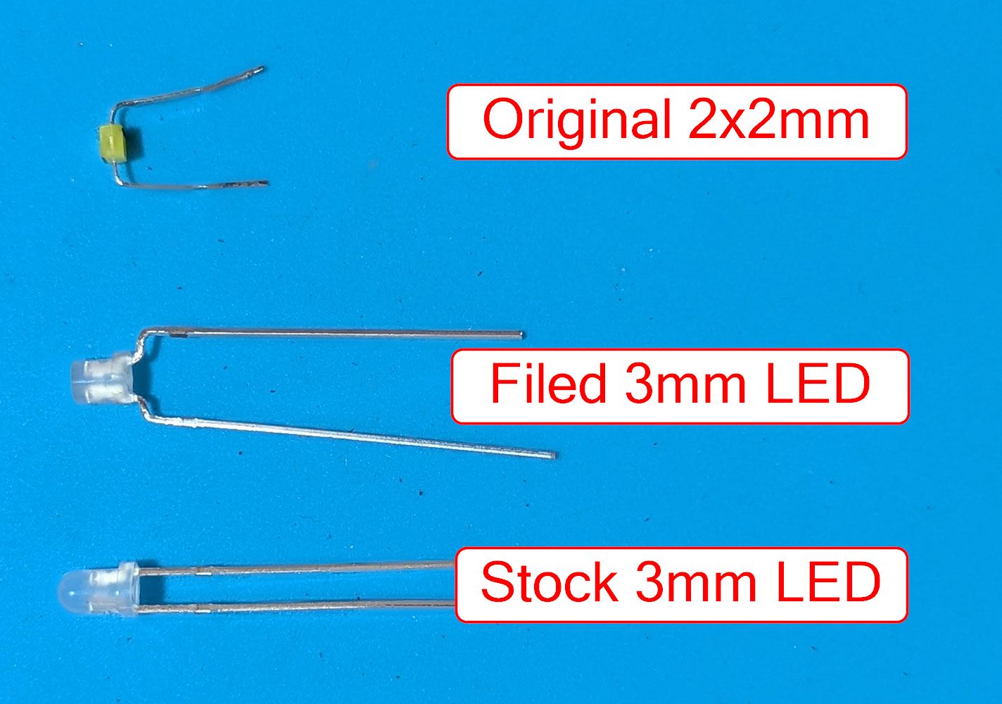
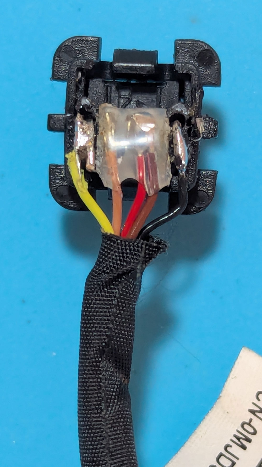
The original component is a 2x2mm rectangular, dual-color (orange/white), 2-pin LED housed in a small cavity. The color changes based on the polarity of the current. I decided to replace it with a standard 3mm, dual-color, 2-pin LED, which costs next to nothing.
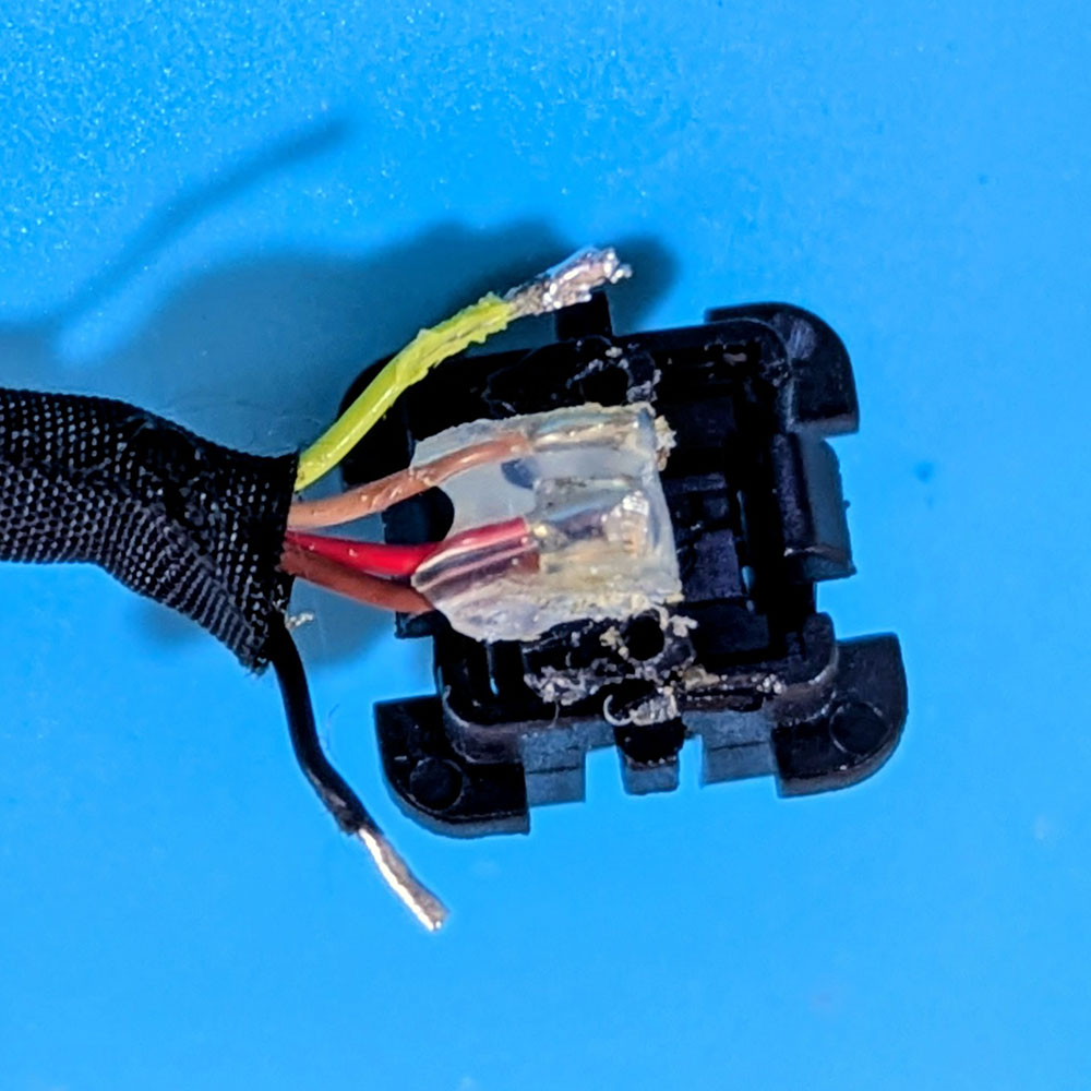
Note: On the small PCB, the LED pins are the two outer pins; the inner pins are for the power switch itself.
The original LED is held in by a hard, silicone-like material. Pro tip: This material is much easier to work with if you use a heated blade. Once you desolder the two outer pins, the old LED should slide out easily.
3) Modifying and Installing the New LED
To fit a standard 3mm LED into a space designed for a 2mm component, I had to make a few simple modifications:
Filing: I filed and polished the top of the LED so it wouldn’t protrude from the cavity and jam the button. I also filed down the flange (the “rim” at the bottom) so it fit inside the housing.
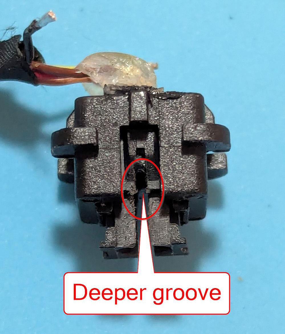
Grooving: I cut the grooves deeper on both sides where the LED pins sit so the LED could sink deeper into the cavity. The cavity is deep enough to take a taller LED.
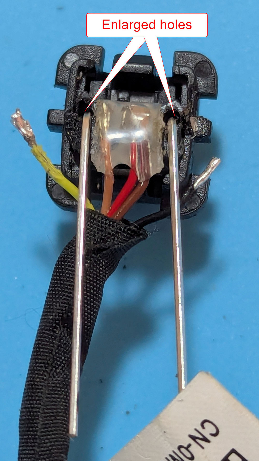
Enlarging: I used a tick needle to slightly enlarge the holes in the plastic right behind the PCB to accommodate the thicker pins of the new LED.
Crucial: Before soldering, ensure the moving parts of the button can travel through their full range without hitting the new LED.
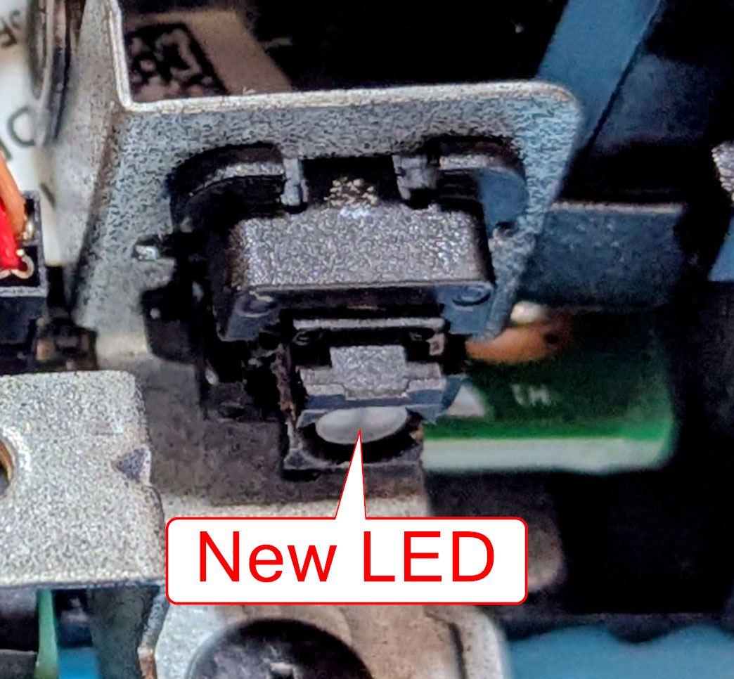
Solder the pins to the outer pads on the mini PCB. Be sure to check the polarity before final assembly so the colors match the PC’s status (White for ON, Orange for Standby).
4) Final Assembly
Once the soldering is complete:
Reinstall the power button into the bracket.
Secure the bracket back into the chassis.
Plug the assembly back into the motherboard.
Replace the speaker and the outer cover.
Note: Before plugging in the power cord, press the button a few times to ensure you hear a clear “click” and that nothing is binding.
If everything was done correctly, your Dell Wyse 5070 should power on with a bright, functioning LED once again!